
Honeywell G2
Honeywell G2
Olarm MAX Installation Guide
Olarm MAX Installation Guide
Last updated: April 7, 2025
Last updated: April 7, 2025
Supported Systems
• G2-12 • G2-20 • G2-44 • G2-44+
📦 What's in the box
Olarm MAX
Internal Power Supply Lid
Super Capacitor With A JST Connecter *Model Dependent
4x Wall Plugs & Screws
2x Enclosure Locking Key
Reversible Peripheral Cable
🛠️ Installation tools required
Drill with a 5mm bit
Phillips-head screwdriver
Flat-head screwdriver
Wire stripper or side cutters
Cable for peripheral wiring (4 Core or 6 Core Comms Cable, 2 core Twin Flex or Ripcord)
Requirements
An Olarm MAX G is required for this installation.
If the Honeywell Galaxy G2 system has an existing Ethernet Module and a third Keypad, these must be removed before installing the Olarm MAX, as it will take their place.
Before proceeding with the installation, check the system and remove the following if present:
Ethernet Module
Keypad 3
Connecting the Olarm Max
Before connecting the Olarm MAX, ensure that you power down your alarm system.
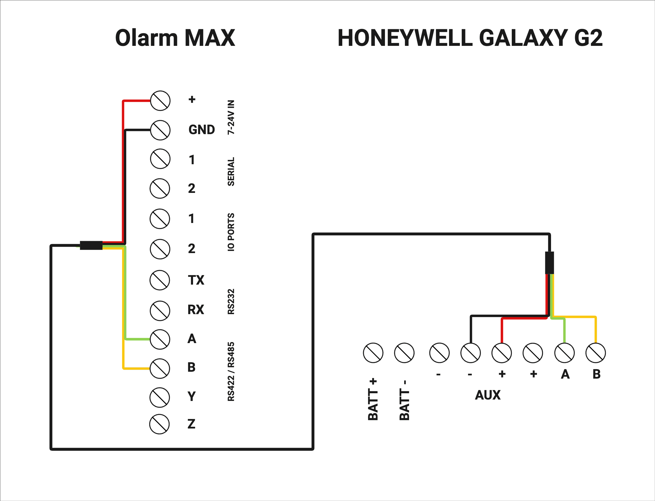
Cut and strip both sides of the reversible peripheral cable. Wire one end of the stripped peripheral cable into the terminals found on the back of the Olarm MAX. And wire the other end of the stripped peripheral cable to the Honeywell Galaxy G2 keypad terminals. You can then power up your alarm system.
See the diagram below for visual reference:
Programme the Honeywell G2
Ensure that the Olarm MAX is wired to the Panel before programming.
Enabling Engineering Mode
Enter the user code and press Enter
Go to location 48 for LVL 3 ACCESS
Ensure LVL 3 ACCESS is set to 1 for Enabled and press Enter to save
Press Escape until you exit the menu
Enter the engineer code and press Enter
Enable signalling via Ethernet module
Go to location 56 for COMMS and press Enter
Go to sub-location 6 for HW Priority and press Enter
Enter the value 4 for Ethernet and press Enter
Ensure Ethernet is set to “1” and press Enter to save
Press Escape once to go back
Configure Alarm Reporting Formats & Triggers
Go to sub-location 4 for Ethernet and press Enter
Enter the value 2 for the Alarm Report menu and press Enter
Press Enter to adjust the Format
Set to “1” for SIA and press Enter
Enter 3 to set SIA Level (0-3) and press Enter
Press Enter to check Triggers
Ensure the following Triggers are set to ON (Press Enter to adjust)
01 - Panic ON
02 - Intruder ON
03 - 24 Hour ON
06 - Fire ON
10 - Set/unset ON
Press Escape two times
Note: Unlisted triggers can be Engineers choice
Configure Alarm Reporting IP Configuration & Account Code
Enter the value 2 for Primary IP and press Enter
Press Enter to check the IP Address
Ensure IP is set to “1.1.1.1” and press Enter
Enter the value 2 for Port No. and press Enter
Ensure Port No. is set to “10002” and press Enter
Press Escape once to go back
Enter the value 4 for Account No. and press Enter
Set to “1234” and press Enter
Press Escape once to go back
Enable Remote Access
Enter the value 3 for Remote Access and press Enter
Press Enter to adjust the Access Period
Set to “0” for Full and press Enter
Enter the value 2 for Access Mode and press Enter
Ensure Access Mode is set to “1” for Direct Access and press Enter
Press Escape twice to go back
Clear Callback No. of Telecoms (IMPORTANT)
Go to sub-location 1 for Telecoms and press Enter
Enter the value 12 for Remote Access and press Enter
Enter the value 3 for Callback No. and press Enter
Clear any value entered by pressing the “B” key
Press Enter to save
Press Escape five times to exit the menu
Perform a Module Scan
Enter the Engineers Code and press Escape
The following modules will be added:
Keypad 3
Ethernet module
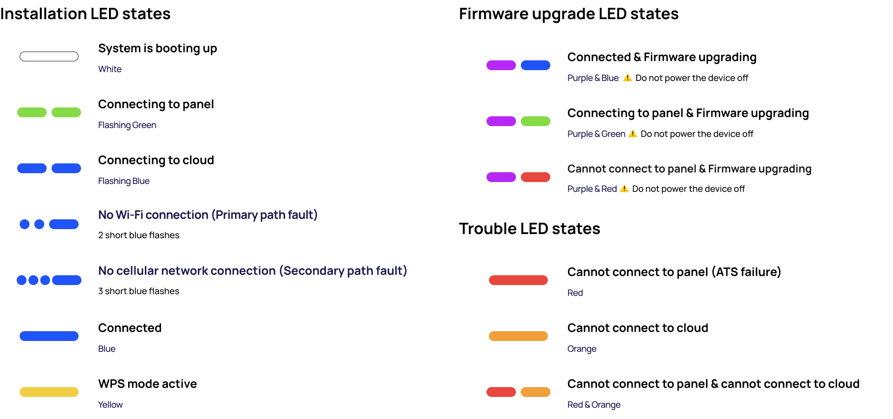
LED States of the Olarm MAX
Power up your Alarm System and Olarm MAX while making reference to the table below for an understanding of the device’s LED states:
Connecting the Olarm MAX to the Olarm APP
There are two methods to add the device to the app. Follow the steps below:
Method 1: QR Code
In the Olarm APP, tap on “Add Device”
Select “Scan QR Code”
You will find the unique QR code on the back of the device beneath the internal power supply compartment. Scan the QR code and follow the prompts.
Method 2: Manually add device
In the Olarm APP, tap on “Add Device”
Select “Enter Serial”
You will find the unique serial number on the back of the device beneath the internal power supply compartment. Enter the serial number in the Olarm APP.
Enter the “V.Code” also found on the back of the device below the serial number and follow the prompts.
Enter the User/Master code in the Olarm APP
All Honeywell Galaxy G2 alarm systems require the User/Master Code in the app for full app functionality, you will be prompted to enter the Master Code.

Connect your device to WiFi
There are two methods to get the Olarm MAX connected to your WiFi network, follow the steps below:
Method 1: In-App Prompt

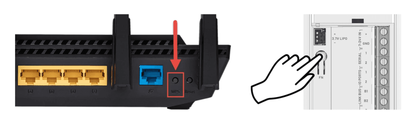
Method 2: WPS Mode
Press the “FN” button found on the back of the Olarm MAX near the screw terminals
This will put the device in WPS Mode for around 3 minutes
On the WiFi router of the network you are wanting to connect to, press the WPS button
The Olarm MAX will automatically pair with the WiFi network
Note: The Olarm MAX only supports 2.4GHz Wi-Fi
Requirements
An Olarm MAX G is required for this installation.
If the Honeywell Galaxy G2 system has an existing Ethernet Module and a third Keypad, these must be removed before installing the Olarm MAX, as it will take their place.
Before proceeding with the installation, check the system and remove the following if present:
Ethernet Module
Keypad 3
Connecting the Olarm Max
Before connecting the Olarm MAX, ensure that you power down your alarm system.
Cut and strip both sides of the reversible peripheral cable. Wire one end of the stripped peripheral cable into the terminals found on the back of the Olarm MAX. And wire the other end of the stripped peripheral cable to the Honeywell Galaxy G2 keypad terminals. You can then power up your alarm system.
See the diagram below for visual reference:
Programme the Honeywell G2
Ensure that the Olarm MAX is wired to the Panel before programming.
Enabling Engineering Mode
Enter the user code and press Enter
Go to location 48 for LVL 3 ACCESS
Ensure LVL 3 ACCESS is set to 1 for Enabled and press Enter to save
Press Escape until you exit the menu
Enter the engineer code and press Enter
Enable signalling via Ethernet module
Go to location 56 for COMMS and press Enter
Go to sub-location 6 for HW Priority and press Enter
Enter the value 4 for Ethernet and press Enter
Ensure Ethernet is set to “1” and press Enter to save
Press Escape once to go back
Configure Alarm Reporting Formats & Triggers
Go to sub-location 4 for Ethernet and press Enter
Enter the value 2 for the Alarm Report menu and press Enter
Press Enter to adjust the Format
Set to “1” for SIA and press Enter
Enter 3 to set SIA Level (0-3) and press Enter
Press Enter to check Triggers
Ensure the following Triggers are set to ON (Press Enter to adjust)
01 - Panic ON
02 - Intruder ON
03 - 24 Hour ON
06 - Fire ON
10 - Set/unset ON
Press Escape two times
Note: Unlisted triggers can be Engineers choice
Configure Alarm Reporting IP Configuration & Account Code
Enter the value 2 for Primary IP and press Enter
Press Enter to check the IP Address
Ensure IP is set to “1.1.1.1” and press Enter
Enter the value 2 for Port No. and press Enter
Ensure Port No. is set to “10002” and press Enter
Press Escape once to go back
Enter the value 4 for Account No. and press Enter
Set to “1234” and press Enter
Press Escape once to go back
Enable Remote Access
Enter the value 3 for Remote Access and press Enter
Press Enter to adjust the Access Period
Set to “0” for Full and press Enter
Enter the value 2 for Access Mode and press Enter
Ensure Access Mode is set to “1” for Direct Access and press Enter
Press Escape twice to go back
Clear Callback No. of Telecoms (IMPORTANT)
Go to sub-location 1 for Telecoms and press Enter
Enter the value 12 for Remote Access and press Enter
Enter the value 3 for Callback No. and press Enter
Clear any value entered by pressing the “B” key
Press Enter to save
Press Escape five times to exit the menu
Perform a Module Scan
Enter the Engineers Code and press Escape
The following modules will be added:
Keypad 3
Ethernet module
LED States of the Olarm MAX
Power up your Alarm System and Olarm MAX while making reference to the table below for an understanding of the device’s LED states:
Connecting the Olarm MAX to the Olarm APP
There are two methods to add the device to the app. Follow the steps below:
Method 1: QR Code
In the Olarm APP, tap on “Add Device”
Select “Scan QR Code”
You will find the unique QR code on the back of the device beneath the internal power supply compartment. Scan the QR code and follow the prompts.
Method 2: Manually add device
In the Olarm APP, tap on “Add Device”
Select “Enter Serial”
You will find the unique serial number on the back of the device beneath the internal power supply compartment. Enter the serial number in the Olarm APP.
Enter the “V.Code” also found on the back of the device below the serial number and follow the prompts.
Enter the User/Master code in the Olarm APP
All Honeywell Galaxy G2 alarm systems require the User/Master Code in the app for full app functionality, you will be prompted to enter the Master Code.
Connect your device to WiFi
There are two methods to get the Olarm MAX connected to your WiFi network, follow the steps below:
Method 1: In-App Prompt
Method 2: WPS Mode
Press the “FN” button found on the back of the Olarm MAX near the screw terminals
This will put the device in WPS Mode for around 3 minutes
On the WiFi router of the network you are wanting to connect to, press the WPS button
The Olarm MAX will automatically pair with the WiFi network
Note: The Olarm MAX only supports 2.4GHz Wi-Fi
Troubleshooting LED States

Mount the Olarm MAX
Follow the diagrams below to mount the Olarm MAX.
Using the screws and wall plugs provided, mount the backplate to the flat surface as shown in the diagram below.
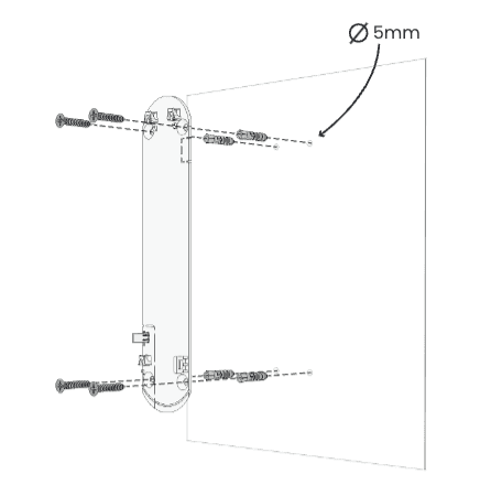
Mounting the backplate to the surface
Place the Olarm MAX flat against the mounted backplate and slide the enclosure down to click into place

Mounting the device to the backplate
Using the locking key, apply force to insert the mechanism into the key hole until flat against the enclosure, which is indicated by two clicks.

Locking the Olarm MAX shut
✅
Final Installation Checklist
Olarm APP
Utilise the Olarm MAX status tab in the app to check your installation

Has the Olarm MAX been added to the user’s app?
Is the device connected to the available onsite Wi-Fi?
Are the in-app functions working?
On & Off
Set voltage
App notifications
Signal Delivery
Has the Alarm Receiving Centre monitoring the Olarm MAX received signals from the device on their relevant monitoring software?
Installation Position
Is the location of installation adequate for a communication device that relies on connectivity?
Are there any peripherals surrounding the device that would interfere with its ability to transmit signals?
Does the distance between Energizer and Olarm MAX exceed 3 metres?
Olarm MAX
Has the required Master/User/Reset Code been entered in the Olarm APP?
Has the external antenna been enabled should there be one installed?
Has the super capacitor been plugged into JST connector?
Has the tamper trigger been tested by unmounting the device?
Should the device be 0G capable, has the the 0G connectivity been tested?
Note:
Do not mount the Olarm MAX inside or against the alarm system enclosure, as this will hinder its connectivity capabilities.
Do not mount the Olarm MAX near any other communication equipment, as they will inter with each others abilities to transmit signals.
Utilise a non-metal enclosure should you mount the Olarm MAX outdoors.
The maximum distance between Olarm MAX and Alarm System is 3 metres.
✅
Final Installation Checklist
Olarm APP
Utilise the Olarm MAX status tab in the app to check your installation
Has the Olarm MAX been added to the user’s app?
Is the device connected to the available onsite Wi-Fi?
Are the in-app functions working?
Arm & Disarm
Panic feature
App notifications
Signal Delivery
Has the Alarm Receiving Centre monitoring the Olarm MAX received signals from the device on their relevant monitoring software?
Installation Position
Is the location of installation adequate for a communication device that relies on connectivity?
Are there any peripherals surrounding the device that would interfere with its ability to transmit signals?
Does the distance between Alarm System and Olarm MAX exceed 3 metres?
Olarm MAX
Has the required Master/UDL Code been entered in the Olarm APP?
Has the external antenna been enabled should there be one installed?
Has the super capacitor been plugged into JST connector?
Has the tamper trigger been tested by unmounting the device?
Should the device be 0G capable, has the the 0G connectivity been tested?
Should the installation require it, has the ATS Fault monitoring been wired, programmed and configured in the APP?
Has the Olarm MAX been added to the user’s app?
Is the device connected to the available onsite Wi-Fi?
Are the in-app functions working?
On & Off
Set voltage
App notifications
Signal Delivery
Has the Alarm Receiving Centre monitoring the Olarm MAX received signals from the device on their relevant monitoring software?
Installation Position
Is the location of installation adequate for a communication device that relies on connectivity?
Are there any peripherals surrounding the device that would interfere with its ability to transmit signals?
Does the distance between Energizer and Olarm MAX exceed 3 metres?
Olarm MAX
Has the required Master/User/Reset Code been entered in the Olarm APP?
Has the external antenna been enabled should there be one installed?
Has the super capacitor been plugged into JST connector?
Has the tamper trigger been tested by unmounting the device?
Should the device be 0G capable, has the the 0G connectivity been tested?
Need help? Contact our support team
Need help? Contact our support team