Texecom

Texecom

Olarm MAX Installation Guide

Olarm MAX Installation Guide

Last updated: May 20, 2024

Last updated: May 20, 2024

Supported Alarm Systems

• Premier Elite 24 • Premier Elite 64 • Elite 64-W • Elite 64-W LIVE • Premier Elite 88 • Premier Elite 168

Olarm MAX

Front

Side

Back

Interior

Front

Olarm MAX

Front

Side

Back

Interior

Front

📦 What's in the box

  • Olarm MAX

  • Internal Power Supply Lid

  • Super Capacitor With A JST Connecter *Model Dependent

  • 4x Wall Plugs & Screws

  • 2x Enclosure Locking Key

  • Reversible Peripheral Cable

🛠️ Installation tools required

  • Drill with a 5mm bit

  • Phillips-head screwdriver

  • Flat-head screwdriver

  • Wire stripper or side cutters

  • Cable for peripheral wiring (4 Core or 6 Core Comms Cable, 2 core Twin Flex or Ripcord)

Programming the Texecom Premier Elite Alarm System

  • Enter the Engineers code (default ‘1234’).
    Note: Enter the user code should this be required for access.

  • Press the ‘Down’ Key until you reach “UDL/Digi Options”, press 'yes/tick'.

  • Press the ‘Down’ Key until you reach “UDL Options”, press 'yes/tick'.

  • Press the ‘Down’ Key until you reach “UDL Password is:”.

  • Press the no/cross to edit it, enter “1234” then press 'yes/tick'.
    Note: Enter any UDL code as per your security requirements.

  • Press the ‘Menu’ key once to go back.

  • Press the ‘Down’ Key until you reach “Com Port Setup:”, press 'yes/tick'.

  • Press the ‘Down’ Key until you reach “Com Port 1”, and press 'no/cross'.
    Note: If Com Port 1 is in use already, simply select "Com Port 2".

  • Press the ‘Down’ Key until you reach “SmartCom”, press 'yes/tick'.

  • Press ‘Menu’ until asked if you want to Exit and Logoff, press 'yes/tick'.


ATS Fault Programming (if required)

  • Enter the Engineers code (default ‘1234’).
    Note: Enter the user code should this be required for access.

  • Press the ‘Down’ Key until you reach 'Global Options', press 'yes/tick'.

  • Press the ‘Down’ Key until you reach 'Monitor Hardware', press 'no/cross'.

  • To activate ATS Path Faults, press '1' until the initial '*' changes to 'P', confirm by pressing 'yes/tick'.
    Note: ATS Path Faults may already be enabled based on your Region.

  • Press ‘Menu’ until asked if you want to Exit and Logoff, press 'yes/tick'.

Wiring the Olarm MAX to the Alarm System

Before connecting the Olarm MAX, ensure that you power down your alarm system.

Cut and strip the 4-pin side of the reversible peripheral cable. Wire the stripped end of the peripheral cable into the terminals found on the back of the Olarm MAX.

Plug the 5-pin side of the peripheral cable to the programmed Com Port on your Texecom Premier Elite Alarm System.

ATS Fault Monitoring (if required)

Should your installation require ATS Fault Monitoring. Connect a wire from IO Port 1 on the Olarm MAX to the L/M (Line Monitoring) terminal on the Texecom Premier Elite Alarm System. Additionally, use a 4.7 kΩ resistor from the DC+ terminal to pull up the L/M terminal.


LED States of the Olarm MAX

Power up your Alarm System and Olarm MAX while making reference to the table below for an understanding of the device’s LED states:


Add the Olarm MAX to the Olarm APP

There are two methods to add the device to the app. Follow the steps below:

Method 1: QR Code

In the Olarm APP, tap on “Add Device”

Select “Scan QR Code”

You will find the unique QR code on the back of the device beneath the internal power supply compartment. Scan the QR code and follow the prompts.

Method 2: Manually add device

In the Olarm APP, tap on “Add Device”

Select “Enter Serial”

You will find the unique serial number on the back of the device beneath the internal power supply compartment. Enter the serial number in the Olarm APP.

Enter the “V.Code” also found on the back of the device below the serial number and follow the prompts.

Enter the UDL code in the Olarm APP

Note: To enable app functionality, you will be prompted to enter the UDL code in the Olarm APP. The UDL code entered needs to match what was programmed on the alarm system.


Connect your device to WiFi

There are two methods to get the Olarm MAX connected to your WiFi network, follow the steps below:

Method 1: In-App Prompt


Method 2: WPS Mode

Press the “FN” button found on the back of the Olarm MAX near the screw terminals

  • This will put the device in WPS Mode for around 3 minutes

  • On the WiFi router of the network you are wanting to connect to, press the WPS button

    • The Olarm MAX will automatically pair with the WiFi network

Note: The Olarm MAX only supports 2.4GHz Wi-Fi


In-App IO Port Configuration for ATS Fault Monitoring (if required)

Follow the in-app steps below to configure the Olarm MAX’s IO Port for ATS Fault Monitoring:


Olarm APP Troubleshooting for Texecom Premier Elite

Should your Olarm APP not be able to arm or disarm. Check that “Remote Arm” & “Remote Disarm” has been enabled for all areas. See the programming steps below:

  • Enter the Engineers code (default ‘1234’).

  • If it says a user needs to grant you access, enter a user code and then retry.

  • Press the ‘Down’ Key until you reach “Area Programming”, press yes/tick.

  • Press the ‘Down’ Key until you reach “Area Options”, press yes/tick.

  • Press the ‘Down’ Key until you reach “Remote Disarm”, press no/cross to edit.

  • Press 1 to enable remote arming for Partition 1.

  • Press 2 to enable remote arming for Partition 2.

  • Continue enabling remote disarming to suit your installation & press tick/yes.

  • Press the ‘Down’ Key until you reach “Remote Arm”, press no/cross to edit.

  • Press 1 to enable remote arming for Partition 1.

  • Press 2 to enable remote arming for Partition 2.

  • Continue enabling remote arming to suit your installation & press tick/yes.

  • Press ‘Menu’ until asked if you want to Exit and Logoff, press yes/tick.

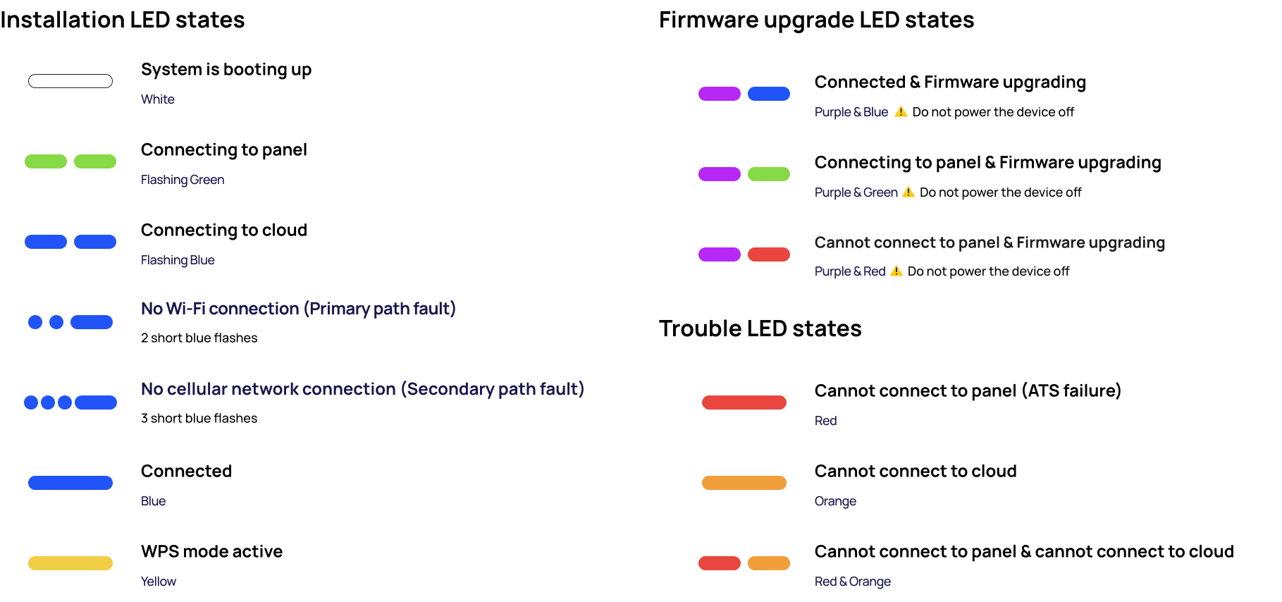
Troubleshooting LED States

Mount the Olarm MAX

Follow the diagrams below to mount the Olarm MAX.

Using the screws and wall plugs provided, mount the backplate to the flat surface as shown in the diagram below.

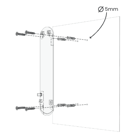
Mounting the backplate to the surface

Place the Olarm MAX flat against the mounted backplate and slide the enclosure down to click into place

Mounting the device to the backplate

Using the locking key, apply force to insert the mechanism into the key hole until flat against the enclosure, which is indicated by two clicks.

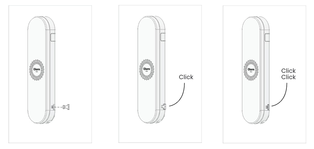
Locking the Olarm MAX shut

Note:

  • Do not mount the Olarm MAX inside or against the alarm system enclosure, as this will hinder its connectivity capabilities.

  • Do not mount the Olarm MAX near any other communication equipment, as they will inter with each others abilities to transmit signals.

  • Utilise a non-metal enclosure should you mount the Olarm MAX outdoors.

  • The maximum distance between Olarm MAX and Alarm System is 3 metres.

Final Installation Checklist

Olarm APP

  • Utilise the Olarm MAX status tab in the app to check your installation

  • Has the Olarm MAX been added to the user’s app?

  • Is the device connected to the available onsite Wi-Fi?

  • Are the in-app functions working?

    • Arm & Disarm

    • Panic feature

    • App notifications

Signal Delivery

  • Has the Alarm Receiving Centre monitoring the Olarm MAX received signals from the device on their relevant monitoring software?

Installation Position

  • Is the location of installation adequate for a communication device that relies on connectivity?

  • Are there any peripherals surrounding the device that would interfere with its ability to transmit signals?

  • Does the distance between Alarm System and Olarm MAX exceed 3 metres?

Olarm MAX

  • Has the required Master/UDL Code been entered in the Olarm APP?

  • Has the external antenna been enabled should there be one installed?

  • Has the super capacitor been plugged into JST connector?

  • Has the tamper trigger been tested by unmounting the device?

  • Should the device be 0G capable, has the the 0G connectivity been tested?

  • Should the installation require it, has the ATS Fault monitoring been wired, programmed and configured in the APP?

Need help? Contact our support team